
Characteristics of Thermistor
Procedure
Components
Thermistor,rheostat,voltmeter,multimeter,oil bath arrangement.
For Real Lab
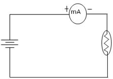
Connections are made as shown in the figure.
Place the thermistor in an oil bath using the heating arrangement.
Note the room temperature (T0).
Turn on the power supply and fix it to a constant voltage.
Note the current readings using a digital multimeter or a milliammeter.
Corresponding resistance is found using the equation:
and is noted as R0.
Vary the temperature of the oil bath using the heating arrangement.
Note the current readings at regular temperature intervals.
Corresponding resistances R are found using the same equation.
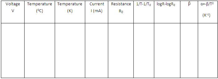
From the readings, logR - logR₀ and 1/T - 1/T₀ are calculated.
Value of β is calculated using the equation:
Temperature coefficient of resistance is found using the equation:
Repeat the experiment for another voltage.
For Simulation
- Click on ‘Show Circuit Diagram’ to display the circuit.
- Place the mouse pointer over the components and click to drag wire.
- After connecting the components, click on the ‘Power On’ button in the variables region
- to start and maintain a constant voltage.
- Select the desired room temperature and choose any thermistor from the drop-down menu.
- The corresponding current reading is shown in the milliammeter.
- Resistance for that voltage value is calculated using the equation:
- Increase the temperature using the slider shown in the variables region.
- Repeat the experiment for different voltage values and different thermistors.
Observations
Result
The material constant of thermistor, = ________
The temperature coefficient of thermistor, = ________ (K-1)